Common pathologies and their causes
Ice Rings
Beamstop

Manhattan Skyline

Missing Rings
Missing Line

Multiplicity Ladder

Separation of Distributions
Background Misestimation

Terracing
Ice Rings
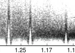
Ice rings are visible in AUSPEX plots as distinct spikes of values in Iobs or Fobs outside of the typical values;
They are Debye-Scherrer rings which can be observed at specific resolutions as a result of X-ray diffraction from a multitude of arbitrarily oriented, typically hexagonal or cubic, ice crystals.
Ice rings can cause problems in data processing and modelling, and may in extreme cases even prevent structure solution.
In AUSPEX, ice rings can be flagged red; however, automatic detection is not as reliable as visual inspection. Hence we give some guidance below what ice rings can look like in AUSPEX plots.

A. AUSPEX plot of Iobs vs. resolution for PDB entry 4EPZ. The resolution ranges corresponding to potential ice rings are marked using grey bars. Two ice rings are clearly visible at high resolution, while the other were successfully modelled in integration. Hence, when identifying ice rings in integrated data, the presence of all ice rings in question is not a reliable criterion. B. Background over- and underestimation: This enlarged view of the ice ring at 1.918 Å shows the effects of insufficient background correction: the blue line shows the background as it is likely assumed by the integration program. The yellow line shows the likely background caused by ice. The discrepancy causes an underestimation of Iobs values left and right of the ice ring, resulting in large negative intensity values, and an overestimation of Iobs in the ice ring, resulting in a peak of Iobs values. However, ice rings do not necessary follow this pattern.
Problem: You had ice on your crystal or sample holder during the measurement. The ice may have been from the cooling of the crystals, or built up during the measurement.
Advice: If possible, try to collect data without ice diffraction. This can be done by optimizing your cryo conditions and the experimental setup. Ensure that all liquid nitrogen used is dry. Sometimes, if ice rings are encountered during measurements, crystals can be rinsed on the holder with liquid nitrogen to remove ice particles from the sample. If this is not possible, or the ice rings are only identified after measurement, you can
- Mask out the ice rings during integration. This will result in a loss of data completeness, see Missing Rings.
- Try to re-integrate with DIALS using the new background estimation for ice rings [Parkhurst, 2017]. The ice ring background estimation is available in DIALS but it is not default.
Essentially, you need to do the following at the moment:
- Integrate as normal: dials.integrate refined_experiments.json refined.pickle
- Run dials.model_background integrated_experiments.json to create background.pickle which contains the global background model
- Run integration again: dials.integrate refined_experiments.json refined.pickle background.algorithm=gmodel gmodel.model=background.pickle
Parkhurst, J. M., Thorn, A., Vollmar, M., Winter, G., Waterman, D. G., Gildea, R. J., Fuentes-Montero, L., Murshudov, G. N. & Evans, G. (2017). IUCrJ, 4, 626–638.
Beamstop
Reflections with intensity or amplitude values near 0 at low resolution indicate that the beam stop was not masked or not masked out completely in integration.
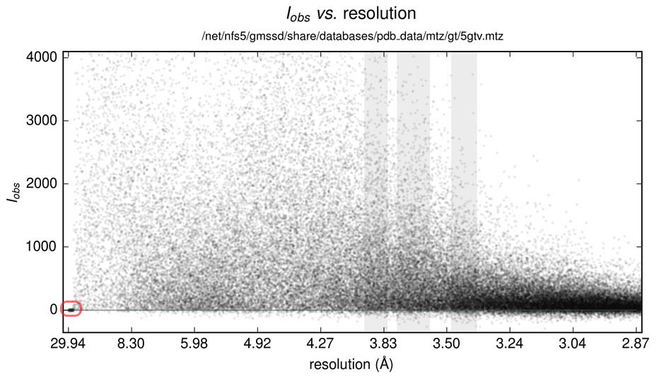
PDB entry 5GTV: The incorrectly integrated reflection are clearly visible at approximately 30 Å resolution (red square), indicating a missing mask for the beam stop.
Problem: These bad low resolution reflections can impair phasing and refinement, in particular if the anomalous signal is to be used.
Advice: Repeat data processing with a correct beam stop mask. If this is not possible, use a suitable low resolution cutoff.
Manhattan Skyline
Data processed with HKL/SCALEPACK can show a strictly resolution-dependent behaviour of Iobs/σ(Iobs) values, where resolution ranges have distinct upper limits for Iobs/σ(Iobs) values. Out of 200 structures processed with HKL/SCALEPACK picked at random from the PDB, including recent submissions, 81 show this type of behaviour. This is because in HKL, data are divided into a number of resolution shells (10, 20, 40, or a user-defined number) and an uncertainty estimate of systematic effects is defined per resolution shell. There is a default value that is uniform for all shells (3%), but users can adjust it. The stepping occurs when the systematic error estimate dominates over the statistical (random) error estimate [Gewirth, 2003], resulting in the plots shown below.
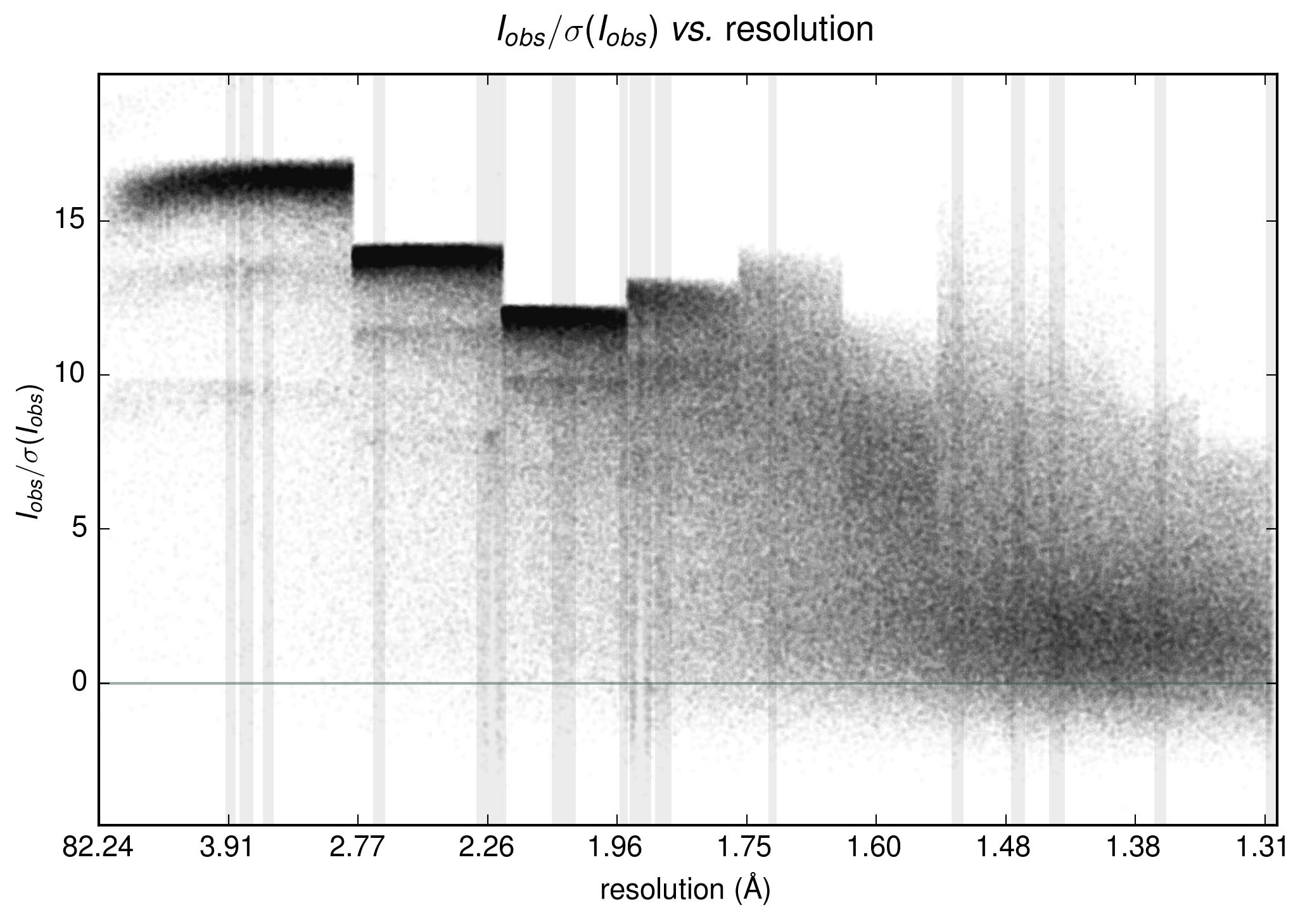
AUSPEX plot of PDB entry 5DEI - resolution-dependence of maximum Iobs/σ(Iobs) is clearly visible at low and medium resolution; there are also ice rings.
Gewirth, D. (2003). HKL Manual. 6th ed. HKL Research, Charlottes-ville, USA.
Missing Rings
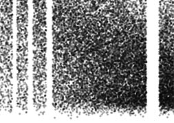
If entire resolution ranges, corresponding to spheres in reciprocal space and rings on an image around the beam stop, are missing, this is typically due to masked-out ice rings.

Image from PDB entry 4PUC; missing data are clearly visible as vertical blocks. Completeness 78.1%.
Problem: This can lead to a high incompleteness of the data.
Advice:
If you have to omit ice ring ranges, cut them exactly so that the biased data are left out.
Try to re-integrate with DIALS using the new background estimation for ice rings [Parkhurst, 2017]. The ice ring background estimation is available in DIALS but it is not default.
Essentially, you need to do the following at the moment:
- Integrate as normal: dials.integrate refined_experiments.json refined.pickle
- Run dials.model_background integrated_experiments.json to create background.pickle which contains the global background model
- Run integration again: dials.integrate refined_experiments.json refined.pickle background.algorithm=gmodel gmodel.model=background.pickle
Parkhurst, J. M., Thorn, A., Vollmar, M., Winter, G., Waterman, D. G., Gildea, R. J., Fuentes-Montero, L., Murshudov, G. N. & Evans, G. (2017). IUCrJ, 4, 626–638.
Missing Line
A missing line between 5.6 and 6.0 Fobs/σ(Fobs) is due to a bug in a lookup table in CTRUNCATE and TRUNCATE respectively.

A missing line in PDB 5AEW, integrated by HKL2000, and converted with TRUNCATE.
Problem: This diminishes your data quality slightly.
Advice: Use intensities where possible, use the newest versions of CTRUNCATE and TRUNCATE where the bug has been removed to convert your data from intensities to amplitudes. If you got this as the result of automatic processing (for example by CrystFEL, HKL2000 or at a synchrotron), please check you have the newest version and if the problem persists, contact the pipeline authors with a link to this site, so that they can upgrade TRUNCATE to the newest version in their pipeline.
Multiplicity Ladder
Plots of Iobs/σ(Iobs) (and plots of Fobs/σ(Fobs) ) vs resolution often show clustering around certain values at low resolution. When considering the associated multiplicity values, it is evident that the higher the multiplicity, the larger is Iobs/σ(Iobs). This is of course because when measurements are summed up, and given that these measurements are independent from each other, their variances are summed up as well.
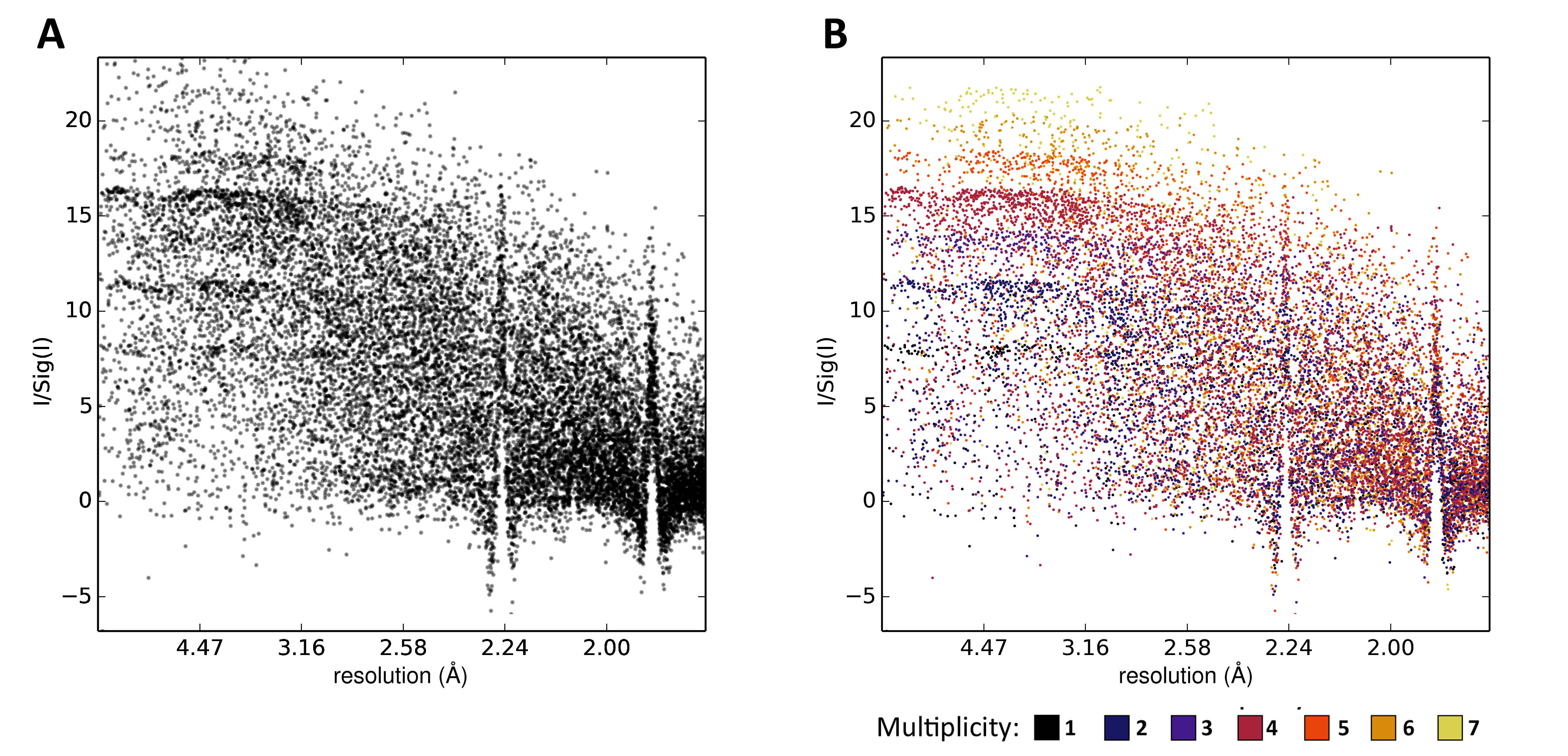
Plot of Iobs/σ(Iobs) vs resolution for PDB 4EPZ. A. At high resolution, ice rings are clearly visible, while at low resolution the values are clustered, forming a ‘ladder-like’ scatter plot. B. The same plot, coloured by multiplicity. The higher the multiplicity, the larger is Iobs/σ(Iobs), hence accounting for the behaviour: The value of a measurement is less uncertain the more often it has been made. At low resolution, the main influence on these values is their multiplicity. In contrast, at high resolution weaker reflections are influenced by other factors.
Problem: None
Advice: Advice: No action is needed to address this.
Diederichs, K. (2010). Acta Cryst. D66, 733–740.
Separation of Distributions
Separation of distributions in σ(F): Effects of conversion from intensities to amplitudes Fobs is needed to calculate electron density maps, and is also used as observations against which many programs optimize structural models. Some exceptions are PHASER where an intensity-based log likelihood target is used to avoid problems related to the conversion from Iobs to Fobs, REFMAC twin refinement and SHELXL which refine against Iobs. This also has the advantage of retaining all statistical properties, some of which (such as negative values) get lost in most conversion methods. Conversion from intensities Iobs to structure factor amplitudes Fobs is usually performed using the French & Wilson algorithm, which uses a Bayesian approach prior that forces negative Fobs values to be positive or 0 valued, and Wilson distributed. This prior may not be approriate if the data are contaminated by ice rings or if other systematic errors are present. The changes introduced by the conversion, as implemented for example in CTRUNCATE, can be illustrated by comparing AUSPEX plots of Iobs/σ(Iobs) with Fobs/σ(Fobs).

A. Iobs/σ(Iobs) vs resolution. B. Fobs/σ(Fobs) does not contain any Fobs/σ(Fobs) equal to or smaller than 0. The centric reflections are visible as a thin line of values lower than the majority of the others (inside the red box). C./D. While the ice rings have high σ(Iobs), σ(Fobs) are dominated by the prior distribution, which is exponential or super exponential, leading to smaller than average σ(Fobs) for the ice-ring reflections. In addition, σ(Fobs) values form two distinct clusters (red dashed ellipses), which is a typical effect of the conversion in CTRUNCATE.
Problem: If your data were statistically not ideally distributed (i.e .Wilson-distributed), this can lead to problems when σ(Fobs) is used.
Advice: Use intensities instead of amplitudes where possible.
Background Misestimation
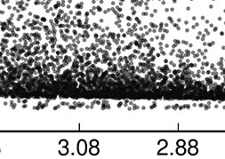
If all intensity values are systematically too high this is due to an incorrect background estimation, which can be the result of a suboptimal background estimation during integration, or stem from a very high background during measurement, for example when the loop holding the crystal was too large, and there is diffuse scattering from the cooled liquid in which the crystal sits.

AUSPEX plot for PDB entry 5KSC: these neutron diffraction data were integrated with MANTID, a program for neutron diffraction data. MANTID is not specialized for protein diffraction, which often contains more background than small molecule diffraction data. This leads to a background-misestimation - the background is not correctly substracted from the reflections and all intensity values are systematically too high.
Problem: This can affect the structure solution.
Advice: Repeat integration with several integration and scaling algorithms; optimize experimental conditions. For neutron data, ask your beamline scientist for additional advice.
Terracing
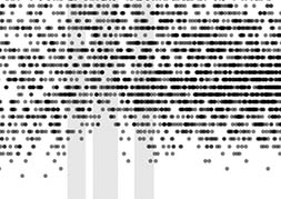
If there are only weak data and, depending on the data processing, discrete values of intensities, amplitudes or sigmas may become visible in plots as 'terraced' values. This is normal.

AUSPEX plot of σ(Iobs) of PDB entry 3QWX, which occupies values between 0 and 8 in discrete steps of 0.1. These discrete values then result in 'terraces' of points in the AUSPEX scatter plot.
Problem: None.
Advice: Use data as is or use a different software for processing.